
A single-phase transformer is a common electrical device widely used in power systems to achieve voltage stepping up or down, electrical isolation, and energy transmission. It operates based on Faraday’s Law of Electromagnetic Induction, transforming voltages by changing the turns ratio between the windings. This article provides a detailed explanation of the working principle of a single-phase transformer, including basic concepts, electromagnetic induction processes, and how voltage transformation is achieved.
The main functions of a single-phase transformer are:
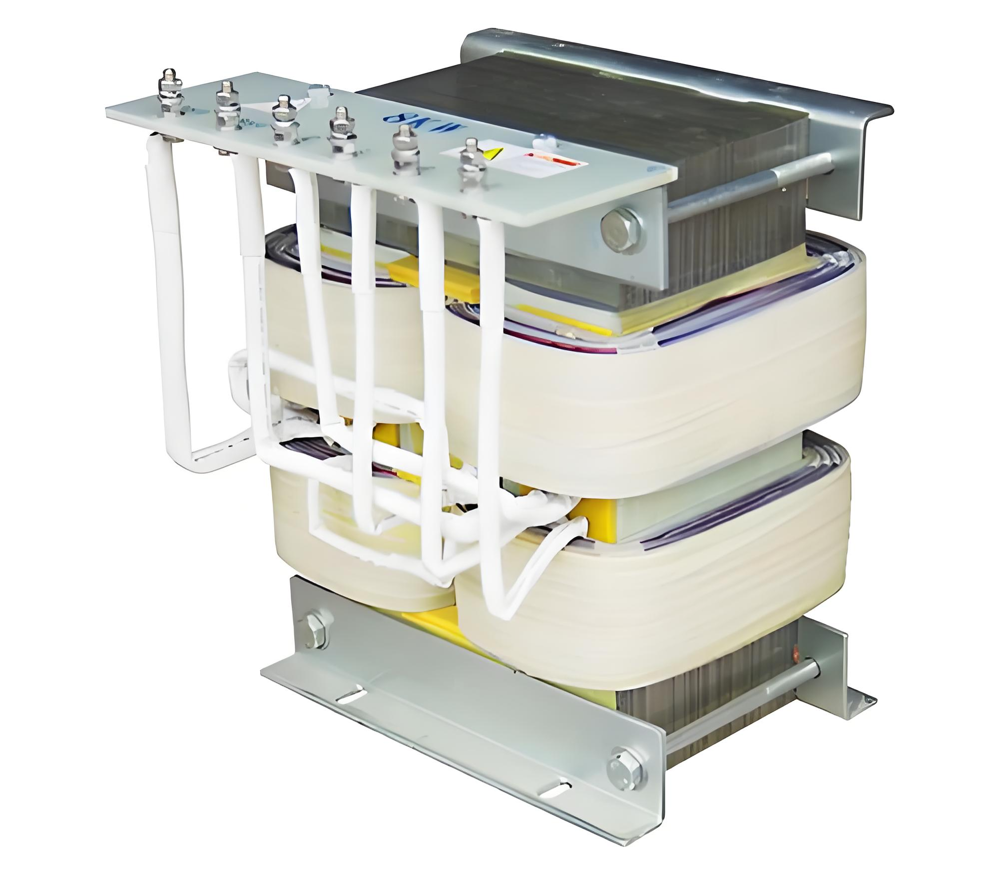
A single-phase transformer consists of several key components:
The operation of a single-phase transformer is based on Faraday’s Law of Electromagnetic Induction, where an alternating current flowing through the primary winding generates an alternating magnetic field in the core. This field passes through the secondary winding and induces an electromotive force (EMF), enabling voltage transformation.
Let be the number of turns in the primary winding and be the number of turns in the secondary winding. The voltage relationship is given by:
Consider a single-phase transformer with 100 turns in the primary winding and 50 turns in the secondary winding. If the input voltage is 220V, the output voltage will be:
This indicates that the transformer is a step-down transformer, delivering an output voltage of 110V.
While the basic formula for voltage transformation is straightforward, several factors influence this process in practical applications:
The variation in magnetic flux directly affects the magnitude of the induced EMF. Ideally, magnetic flux should remain constant, but in practice, it may be influenced by factors such as core saturation.
Due to the non-ideal nature of core materials, core losses like eddy current and hysteresis losses can impact transformer efficiency.
Resistance within the windings leads to power loss, especially under high current conditions. Choosing appropriate conductive materials (such as copper wire) is crucial.
Leakage inductance between the windings means that some magnetic flux does not effectively couple into the secondary winding, affecting voltage transformation.
Used to step down high-voltage transmission line voltages to household levels of 220V or 110V.
Single-phase transformers provide isolated power for brakes, door drives, and control circuits in elevators.
Commonly used in commercial buildings and street lighting to supply safe and stable voltage to lamps.
Applications include machine tool controls, automation instruments, and small motor drives.
A single-phase transformer achieves voltage transformation, electrical isolation, and energy transmission using Faraday’s Law of Electromagnetic Induction. Understanding its working principle aids in better selection, design, and maintenance. Whether in residential power supply, industrial control, or lighting systems, single-phase transformers play a critical role.


