
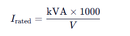
where:
- V = rated voltage (line-to-line for three-phase, line-to-neutral or line-to-line for single-phase as applicable),
- I = rated current,
- The factor of 1000 converts VA to kVA.
This rating assumes operation at nominal frequency (50/60 Hz), standard ambient temperature (typically 40°C), and sinusoidal waveforms.
3. Rated Current Calculation Formulas
The method differs based on whether the transformer is single-phase or three-phase.
3.1 Single-Phase Transformers
For a single-phase transformer:
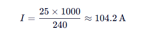
Example:
A 25 kVA, 240 V single-phase transformer:
3.2 Three-Phase Transformers

Example:
A 25 kVA, 240 V single-phase transformer:

This current applies to both primary and secondary sides when using their respective rated voltages.
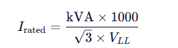
3.2 Three-Phase Transformers
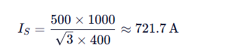
For three-phase systems, the relationship includes the square root of three ( 3 ) due to line-to-line voltage geometry:

where VLL is the line-to-line voltage.
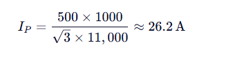
Example:
A 500 kVA, 11 kV/400 V three-phase transformer:
A 500 kVA, 11 kV/400 V three-phase transformer:
- Primary current:
- Secondary current:
- These values are critical for selecting circuit breakers, fuses, busbars, and conductors.


4. Key Considerations in Rating and Current Calculations
a) Voltage Taps and Tolerance
Transformers often include ±5% or ±2×2.5% tap changers. Rated current should be calculated using the nominal voltage, but protection settings must account for possible tap variations.
b) Delta vs. Wye (Star) Connections
- In delta-connected windings, phase current = line current / .
- In wye-connected windings, phase voltage = line voltage /
- While rated line currents are used for external protection and cabling, internal winding currents differ based on connection type—important for thermal modeling.
c) Ambient Temperature and Derating
If installed in environments above 40°C, the transformer may require derating per IEEE C57.91 or IEC 60076-7. For example, a 1000 kVA unit at 50°C ambient might only support 900 kVA continuously.
d) Overload Capability
Transformers can handle short-term overloads (e.g., 150% for 1 hour) if thermally permissible, but continuous operation must respect the nameplate kVA rating.
5. Practical Applications
a) Sizing for Load Requirements
To select a transformer, sum the connected load in kVA (not kW), including diversity and future growth:


b) Protection Coordination
Rated currents determine:
- Fuse ratings (typically 125–150% of full-load current for primary protection),
- Circuit breaker settings,
- Relay pickup values for differential or overcurrent protection.
c) Short-Circuit Current Estimation
Transformer impedance (%Z) and rated current allow estimation of available fault current:


This is vital for switchgear and equipment withstand ratings.
6. Common Mistakes to Avoid
- Using kW instead of kVA for sizing → leads to undersized transformers.
- Ignoring three-phase factor ( ) → results in 57.7% current underestimation.
- Confusing phase and line quantities in delta/wye systems.
- Neglecting harmonics in non-linear loads (e.g., data centers), which increase RMS current and require K-rated transformers.
-
7. Conclusion
Transformer capacity and rated current calculations form the backbone of power system design. Mastery of these fundamentals ensures that transformers operate within thermal and electrical limits, deliver reliable service, and integrate safely with protective devices. As grids incorporate more variable renewable generation and power electronics, accurate rating analysis remains indispensable—not only for new installations but also for retrofitting aging infrastructure. Engineers must combine theoretical formulas with practical standards (IEEE, IEC, NEC) to achieve optimal performance, safety, and longevity.

