Copper Loss
Definition and Principle
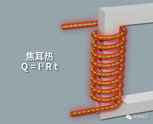
Copper plays a crucial role in transformers, as transformer windings are typically made of copper wire. The "copper loss" in a transformer refers to the loss generated by the copper wire. Transformer "copper loss," also known as load loss, is a variable loss that changes depending on operating conditions. When the transformer operates under load, current flows through the winding, and due to the resistance of the conductor, resistive losses occur. According to Joule's Law, this resistance generates heat when current flows through it, and the greater the current, the higher the power loss. Therefore, resistive losses are proportional to the square of the current and independent of voltage. Since copper loss varies with the magnitude of the current, it is referred to as a variable loss and represents one of the primary losses during transformer operation.
Influencing Factors
- Current Magnitude: As mentioned above, copper loss is proportional to the square of the current, making current magnitude a key factor influencing copper loss.
- Winding Resistance: The resistance of the winding directly affects copper loss. Higher resistance results in higher copper loss.
- Number of Coil Layers: More coil layers increase the length of the current path in the winding, which raises the resistance and, consequently, copper loss.
- Switching Frequency: The impact of switching frequency on copper loss depends on the transformer's distributed parameters and load characteristics. When the load characteristics and distributed parameters exhibit inductive behavior, copper loss decreases with increasing switching frequency. Conversely, when they exhibit capacitive behavior, copper loss increases with switching frequency.
- Temperature Effects: Load loss is also influenced by the transformer's temperature. Additionally, leakage flux caused by load current induces eddy current losses within the winding and stray losses in external metal components.
Calculation Methods
There are two main formulas for calculating copper loss:
-
Based on Rated Current and Resistance:
Copper Loss (kW)=I2×Rc×Δt
Where I is the rated current of the transformer, Rc is the resistance of the copper wire, and Δt is the operating time of the transformer.
-
Based on Rated Current and Total Copper Resistance:
Copper Loss=I2×R
Where I is the rated current of the transformer, and R is the total copper resistance of the transformer. The total copper resistance R can be calculated as:
R=2R1+R2
Here, R1 is the primary side copper resistance, and R2 is the secondary side copper resistance.
Methods to Reduce Copper Loss
- Increase the cross-sectional area of the transformer winding to reduce conductor resistance, thereby effectively lowering copper loss.
- Use high-quality conductive materials such as copper foil or aluminum foil to reduce winding resistance.
- Minimize light-load operation time to limit the proportion of time the transformer operates under light load, which helps reduce copper loss.
Iron Loss
Definition and Principle
Unlike copper loss, iron loss in transformers is unrelated to factors such as windings or current magnitude. As the name suggests, iron loss is associated with the core. Transformer iron loss is also called "no-load loss" because it exists regardless of whether the transformer is fully loaded or unloaded. It is considered a fixed loss. However, under load conditions, power loss decreases as electric field strength diminishes.
Classification
Transformer iron loss is divided into two categories: hysteresis loss and eddy current loss.
- Hysteresis Loss: The working principle of a transformer is based on electromagnetic induction to achieve voltage transformation and current changes. During operation, magnetic flux flows through the core. The core exhibits magnetic resistance to the magnetic flux, similar to how a conductor exhibits resistance to current, generating heat. This type of loss is called "hysteresis loss."
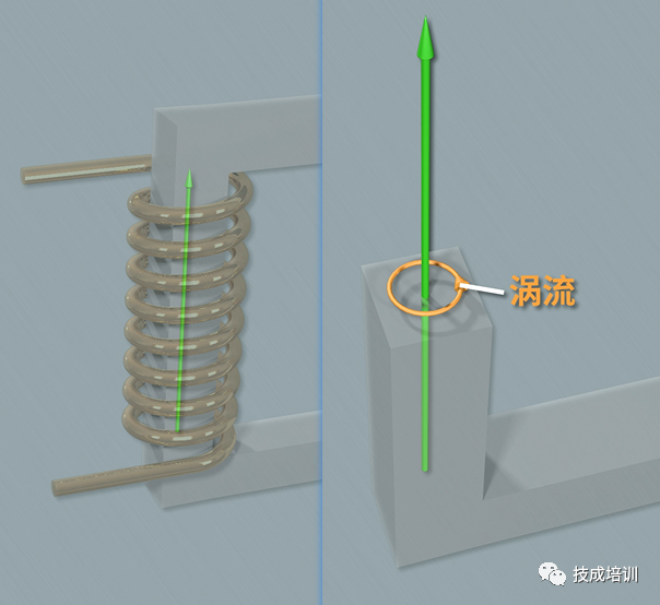
- Eddy Current Loss: When the primary winding of the transformer is energized, the magnetic flux generated by the coil flows through the core. Since the core itself is conductive, an electromotive force is induced on planes perpendicular to the magnetic lines of force. This electromotive force forms a closed loop on the core’s cross-section, creating a circulating current resembling a vortex, hence the term "eddy current." The loss caused by this eddy current is called "eddy current loss." To minimize eddy currents, the core is constructed as thin laminations because thinner laminations have higher resistance, reducing the current.
Influencing Factors
- Operating Voltage and Frequency: Iron loss is related to the transformer's operating voltage and frequency, as these factors affect the magnetic field strength and hysteresis phenomenon in the core.
- Core Material: The magnetic hysteresis properties of the core material influence the magnitude of iron loss. Poorly selected core materials can increase hysteresis loss.
- Manufacturing Process: The manufacturing process of the transformer also impacts iron loss. For example, the stacking method of the core laminations and insulation treatments affect the level of iron loss.
Calculation Methods
There are two main formulas for calculating iron loss:
-
Based on Rated Current and Hysteresis/Resistance Loss:
Iron Loss (kVA)=I2×(Rm+Ra)
Where I is the rated current of the transformer, Rm is the hysteresis loss of the core, and Ra is the resistance loss of the core.
-
Based on Constants, Flux Density, and Operating Frequency:
Piron=Kf×Bm2×f
Where Piron is the iron loss, Kf is a constant, Bm is the flux density, and f is the operating frequency of the transformer.
Methods to Reduce Iron Loss
- Select high-quality core materials with low hysteresis loss to reduce iron loss.
- Optimize the manufacturing process by improving the stacking method of core laminations and enhancing insulation treatments to lower iron loss.
- Optimize design during the transformer design phase by refining structural design and parameter selection to minimize iron loss.


