The voltage conversion mechanism of a three-phase isolation transformer is rooted in the principles of electromagnetic induction and mutual coupling between its primary and secondary windings. This process ensures efficient power transfer while maintaining galvanic isolation between the input and output circuits. Below, we delve into the technical details of how this mechanism operates.
1. Fundamental Principle: Electromagnetic Induction
The operation of a three-phase isolation transformer relies on Faraday's Law of Electromagnetic Induction, which states that a changing magnetic flux induces an electromotive force (EMF) in a conductor. In a three-phase isolation transformer, the following sequence occurs:
-
Primary Winding Excitation:
- When a three-phase alternating current (AC) voltage is applied to the primary winding, it generates a time-varying magnetic flux in the transformer's core.
- The magnetic flux alternates sinusoidally at the same frequency as the input voltage.
-
Magnetic Flux Linkage:
- The magnetic flux produced by the primary winding links with the secondary winding through the shared magnetic core. This linkage ensures efficient energy transfer without direct electrical contact.
-
Secondary Winding Induction:
- As the alternating magnetic flux passes through the secondary winding, it induces an EMF in accordance with Faraday's Law. The magnitude of the induced voltage depends on the number of turns in the secondary winding relative to the primary winding.
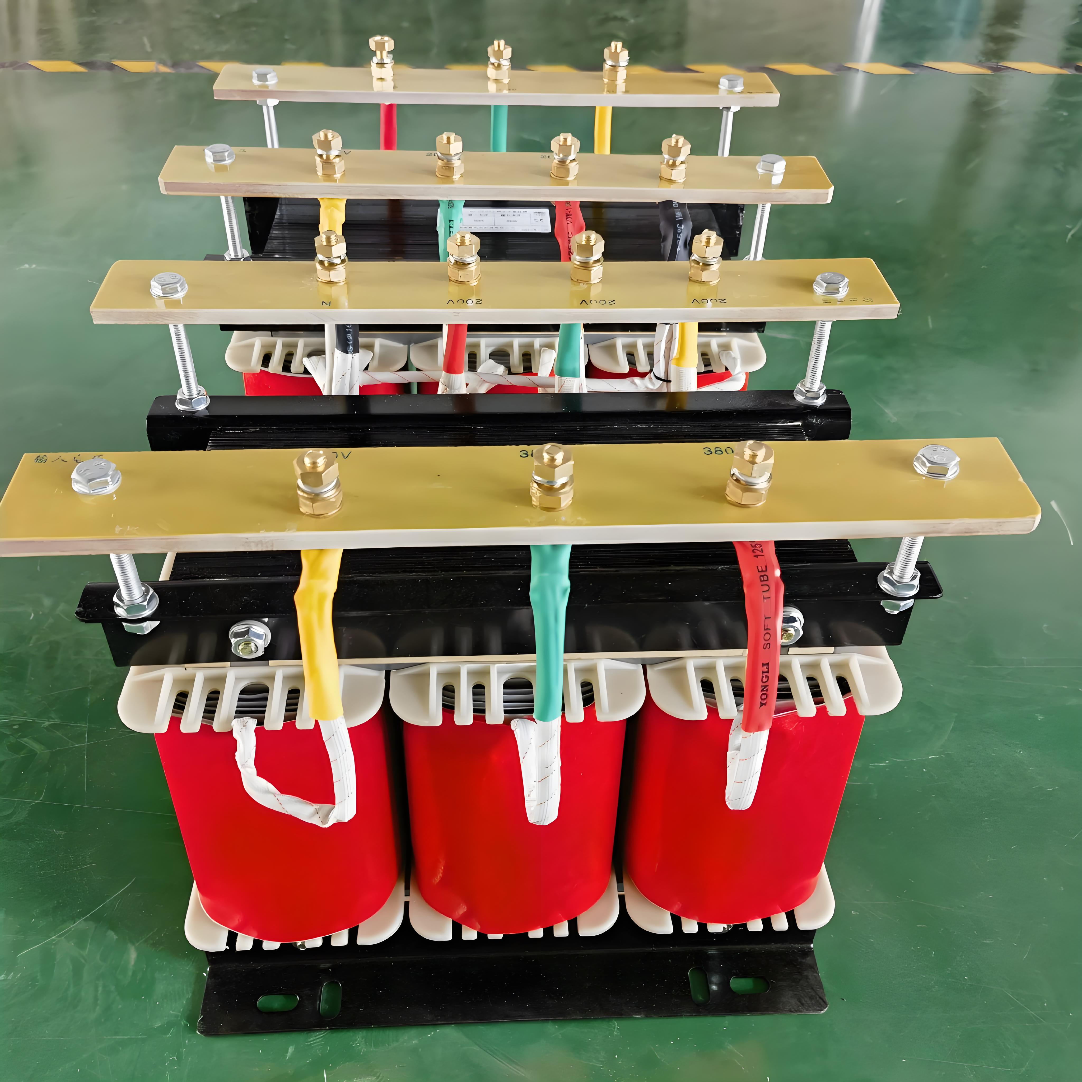
2. Turns Ratio and Voltage Transformation
The voltage conversion in a three-phase isolation transformer is determined by the turns ratio (N1:N2), where:
- N1: Number of turns in the primary winding
- N2: Number of turns in the secondary winding
The relationship between the input voltage (V1) and output voltage (V2) is given by:
V2V1=N2N1
- Step-Up Transformer: If N2>N1, the secondary voltage is higher than the primary voltage.
- Step-Down Transformer: If N2<N1, the secondary voltage is lower than the primary voltage.
- Isolation Without Voltage Change: If N2=N1, the transformer provides electrical isolation without altering the voltage level.
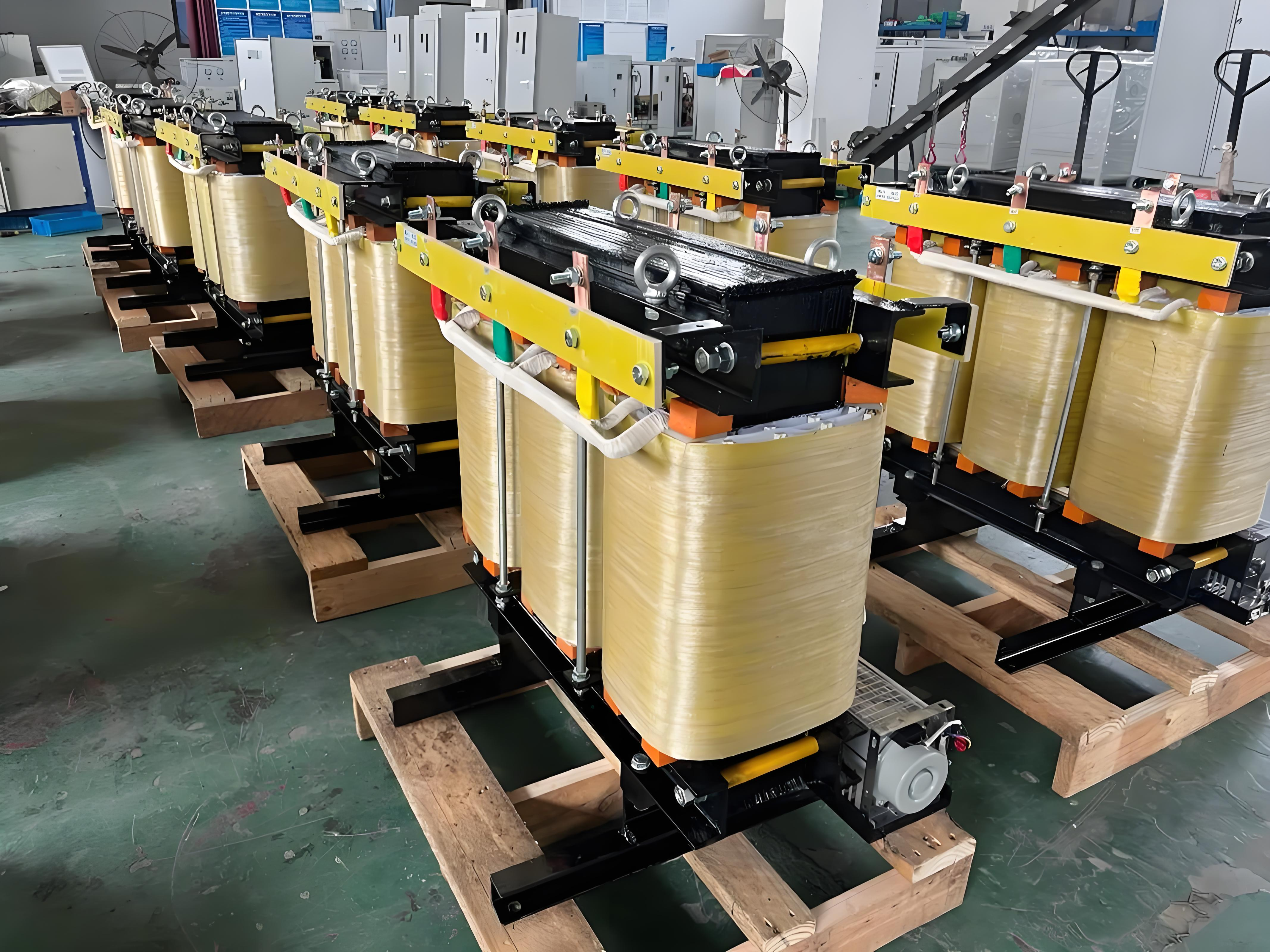
3. Three-Phase Configuration and Voltage Balancing
In a three-phase system, the transformer typically employs one of the following winding configurations:
-
Delta-Delta (Δ-Δ):
- Both primary and secondary windings are connected in a delta configuration.
- Suitable for balanced three-phase systems without neutral connections.
-
Wye-Wye (Y-Y):
- Both primary and secondary windings are connected in a wye configuration.
- Provides a neutral point for single-phase loads and ensures balanced voltage distribution.
-
Delta-Wye (Δ-Y):
- Primary winding is delta-connected, and secondary winding is wye-connected.
- Commonly used in distribution systems to step down voltages while providing a neutral point.
-
Wye-Delta (Y-Δ):
- Primary winding is wye-connected, and secondary winding is delta-connected.
- Often used for stepping down voltages in industrial applications.
Each configuration affects the phase relationship and voltage levels between the primary and secondary sides, ensuring compatibility with the load requirements.
4. Galvanic Isolation and Voltage Stabilization
A key feature of three-phase isolation transformers is their ability to provide galvanic isolation, which separates the input and output circuits electrically. This isolation serves several purposes:
-
Safety:
- Prevents direct electrical contact between the primary and secondary sides, reducing the risk of electric shock and equipment damage.
-
Noise Suppression:
- Blocks the transmission of electrical noise, harmonics, and transient surges from the primary side to the secondary side.
-
Voltage Stabilization:
- Some isolation transformers incorporate taps or additional windings to regulate output voltage, compensating for fluctuations in the input supply.
5. Harmonic Mitigation and Power Quality Improvement
Three-phase isolation transformers also play a role in mitigating harmonic distortions and improving power quality:
-
Harmonic Attenuation:
- The transformer's design can reduce the propagation of harmonics from the source to the load, ensuring cleaner power delivery.
-
Phase Balance:
- Proper winding configurations help maintain phase balance, minimizing voltage imbalances and improving system efficiency.
-
Transient Protection:
- The transformer's inductive nature dampens voltage spikes and transients, protecting sensitive equipment downstream.
6. Practical Considerations in Voltage Conversion
When designing or selecting a three-phase isolation transformer for voltage conversion, consider the following factors:
-
Load Characteristics:
- Evaluate whether the load is balanced or unbalanced and whether it requires a neutral connection.
-
Efficiency:
- Ensure minimal losses during voltage conversion to maximize energy efficiency.
-
Insulation and Dielectric Strength:
- Verify that the insulation materials can withstand the maximum operating voltage and transient conditions.
-
Cooling Requirements:
- Assess the cooling method (natural air, forced air, or oil-immersed) based on the transformer's capacity and operating environment.


